Tuesday 18 December 2012
Monday 17 December 2012
DEFINITION OF CIVIL ENGINEERING:
Civil engineering is field of engineering sciences, related to design, construction and maintenance of buildings, dams, bridges, tunnels, highways and other structures by the use of physical laws, mathematical equations and theories of mechanics. Civil Engineers utilize the available resources (expertise, materials, manpower) to complete the project in the given time span keeping in view the time, expenditure, environmental issues and physical hazards of the project.
 Also known as the mother of all engineering, it is
the oldest, broadest, most simple and useful of all engineering
sciences. Being a broader field Civil Engineering is divided into the
following sub-categories and / or fields.
Also known as the mother of all engineering, it is
the oldest, broadest, most simple and useful of all engineering
sciences. Being a broader field Civil Engineering is divided into the
following sub-categories and / or fields.
Civil Engineer is able to do the following jobs:.....
Scope of Civil Engineering
Due to increase in the scope of civil engineering with the passage of time, it has now got diversified into many branches of study. Some of the significant ones include structural engineering, geotechnical engineering, transportation engineering, hydraulic engineering, environmental engineering and a few more important areas of study.
Engineers are employed by a wide range of companies in the United States, from small start up businesses focused on a new invention idea to large-scale companies that work on immense contracts. Engineers from different fields constantly work together to create successful products. When considering the design and manufacture of an aircraft, for example, the workforce behind the development will include aeronautical engineers optimizing airflow paths, analysis engineers evaluating the strength of landing gear developed by design engineers, electronics engineers developing wiring methods and pilot controls, ergonomic engineers designing comfortable seating and computer engineers programming the aircraft operation systems, including everything from the autopilot system to the cabin crew call system.
STUDY BASE:Civil engineers work in a fast-moving, challenging and rewarding profession, involving design, construction and management. You could be involved in seeing through a project from design stage to construction and competition. These projects might include the development and construction of bridges, tunnels, roads, railways, dams and major buildings. There is also the chance to work overseas and starting salaries have increased at double the rate of inflation over the last five years, as many sectors of civil engineering experience skills shortages. Interested? Read on ...
We look for individuals that have the appropriate degree and who can demonstrate their understanding of the technical element of civil engineering. In terms of personal attributes, we look for graduates who are self-motivated and have good communication skills. The latter is critical as our business is a consultancy and you need to articulate and engage with customers and colleagues. Team working and the ability to co-operate with a variety of individuals in a multidisciplinary team is also something that we look for. We find out at the point of recruitment what area of business our graduates are interested in.
Every graduate civil engineer who joins us will follow our accredited professional development scheme with the aim of becoming chartered. This involves continuous professional development, but we also provide a comprehensive portfolio of training to further enhance their knowledge, skills and outlook, which looks at the softer skills such as communication and judgment.
In our firm, once you have your chartership, then it's down to you which route you want to take. We have three career routes: a project route, technical route or business route.
The types of projects graduates could be working on might include flood defence work for the Environment Agency, cycle way improvements for local authorities and motorway widening for the Highways Agency. They might be seconded to work on an overseas project in Dubai, China or Europe. Some of the projects we're working on include Crossrail, the M1 widening and Dubai Metro (the emirate's first mass transit system).
We normally look for people with a maths A-level at a high grade on our civil engineering degree courses. We're looking for people with enthusiasm and a real interest in civil engineering, not people who want to use an engineering degree as a stepping stone for working in the City.
For both our four-year MEng and three-year BEng in civil engineering, we offer an optional industrial placement for a year. We encourage people to get work experience, as those students on placements can put their learning into context and are much more enthusiastic when they come back to the course.
We have got the following core modules in our courses: structures, maths, material science, geotechnics, building environment and hydraulics. Alongside that, students will work on a series of design projects which help them apply what they have been learning in lectures. In the final-year project, engineers and architectural students work together on a large project. Last year they designed the British pavilion for the World Expo in China.
I did graphical communications, maths and physics at A-Level and wanted to go into structural engineering. I was really interested in finding out how buildings stood up and how they were constructed. I did a four-year degree in civil engineering at the University of Bath and in my second and third year I worked in industry. I then went to work at Faber Maunsell and was put on an internal guide scheme accredited by the Institute of Civil Engineers (ICE). It took me three-and-a-half years to complete my training. I took my ICE chartership exam in April this year.
I've just been promoted to senior engineer and it's a varied job. On a typical day, I'll spend time modelling a structure using computer analysis or if a project is being built, then I'll do a site visit. One of my first projects that I worked on was as part of the design team for Halley VI, the base for the British research station in Antarctica. I went out to work on the existing base (Halley V) in December 2005 to April 2006. This was on secondment to the British Antarctic Survey to supervise structural works to its existing base.
The perks of the job are being able to come up with a concept building and then seeing your building three to four years later - to actually see the tangible results of your work.
Civil engineering is field of engineering sciences, related to design, construction and maintenance of buildings, dams, bridges, tunnels, highways and other structures by the use of physical laws, mathematical equations and theories of mechanics. Civil Engineers utilize the available resources (expertise, materials, manpower) to complete the project in the given time span keeping in view the time, expenditure, environmental issues and physical hazards of the project.
- Geo technical Engineering
- Structural Engineering
- Transportation Engineering
- Water Resource engineering
- Environmental Engineering
- Earthquake Engineering
- Urban Planning
What does a Civil Engineer do????
A Civil Engineer is responsible for planning, design, construction and/or maintenance of structures. Civil Engineer can work in private constructions companies, governmental public works organizations or in universities as a research fellow or a teacher. A civil Engineer can be a surveyor, a technical report writer or even a project manager.Civil Engineer is able to do the following jobs:.....
Scope of Civil Engineering
Due to increase in the scope of civil engineering with the passage of time, it has now got diversified into many branches of study. Some of the significant ones include structural engineering, geotechnical engineering, transportation engineering, hydraulic engineering, environmental engineering and a few more important areas of study.
Engineers are employed by a wide range of companies in the United States, from small start up businesses focused on a new invention idea to large-scale companies that work on immense contracts. Engineers from different fields constantly work together to create successful products. When considering the design and manufacture of an aircraft, for example, the workforce behind the development will include aeronautical engineers optimizing airflow paths, analysis engineers evaluating the strength of landing gear developed by design engineers, electronics engineers developing wiring methods and pilot controls, ergonomic engineers designing comfortable seating and computer engineers programming the aircraft operation systems, including everything from the autopilot system to the cabin crew call system.
STUDY BASE:Civil engineers work in a fast-moving, challenging and rewarding profession, involving design, construction and management. You could be involved in seeing through a project from design stage to construction and competition. These projects might include the development and construction of bridges, tunnels, roads, railways, dams and major buildings. There is also the chance to work overseas and starting salaries have increased at double the rate of inflation over the last five years, as many sectors of civil engineering experience skills shortages. Interested? Read on ...
An employer says ...
Karen Wallbridge, head of recruitment at engineering consultancy Atkins (atkinsglobal.com)We look for individuals that have the appropriate degree and who can demonstrate their understanding of the technical element of civil engineering. In terms of personal attributes, we look for graduates who are self-motivated and have good communication skills. The latter is critical as our business is a consultancy and you need to articulate and engage with customers and colleagues. Team working and the ability to co-operate with a variety of individuals in a multidisciplinary team is also something that we look for. We find out at the point of recruitment what area of business our graduates are interested in.
Every graduate civil engineer who joins us will follow our accredited professional development scheme with the aim of becoming chartered. This involves continuous professional development, but we also provide a comprehensive portfolio of training to further enhance their knowledge, skills and outlook, which looks at the softer skills such as communication and judgment.
In our firm, once you have your chartership, then it's down to you which route you want to take. We have three career routes: a project route, technical route or business route.
The types of projects graduates could be working on might include flood defence work for the Environment Agency, cycle way improvements for local authorities and motorway widening for the Highways Agency. They might be seconded to work on an overseas project in Dubai, China or Europe. Some of the projects we're working on include Crossrail, the M1 widening and Dubai Metro (the emirate's first mass transit system).
A university says ...
Antony Darby, admissions tutor for civil engineering at the University of Bath (bath.ac.uk)We normally look for people with a maths A-level at a high grade on our civil engineering degree courses. We're looking for people with enthusiasm and a real interest in civil engineering, not people who want to use an engineering degree as a stepping stone for working in the City.
For both our four-year MEng and three-year BEng in civil engineering, we offer an optional industrial placement for a year. We encourage people to get work experience, as those students on placements can put their learning into context and are much more enthusiastic when they come back to the course.
We have got the following core modules in our courses: structures, maths, material science, geotechnics, building environment and hydraulics. Alongside that, students will work on a series of design projects which help them apply what they have been learning in lectures. In the final-year project, engineers and architectural students work together on a large project. Last year they designed the British pavilion for the World Expo in China.
A graduate says ...
Gemma Clarke, senior engineer at engineering and design consultancy, Faber Maunsell (fabermaunsell.com)I did graphical communications, maths and physics at A-Level and wanted to go into structural engineering. I was really interested in finding out how buildings stood up and how they were constructed. I did a four-year degree in civil engineering at the University of Bath and in my second and third year I worked in industry. I then went to work at Faber Maunsell and was put on an internal guide scheme accredited by the Institute of Civil Engineers (ICE). It took me three-and-a-half years to complete my training. I took my ICE chartership exam in April this year.
I've just been promoted to senior engineer and it's a varied job. On a typical day, I'll spend time modelling a structure using computer analysis or if a project is being built, then I'll do a site visit. One of my first projects that I worked on was as part of the design team for Halley VI, the base for the British research station in Antarctica. I went out to work on the existing base (Halley V) in December 2005 to April 2006. This was on secondment to the British Antarctic Survey to supervise structural works to its existing base.
The perks of the job are being able to come up with a concept building and then seeing your building three to four years later - to actually see the tangible results of your work.
CAREER IN CIVIL ENGINEERING: ince time immemorial, human beings have been engaged in building all
kinds of edifices. From huts made of mud to Taj Mahal, we have
definitely come a long way. As civilisations matured, it simultaneously
led to the development of bigger, better and diverse structures. From
cave dwellings, human beings had moved on to construct houses, palaces,
canals, dams, highways, and stadia. These civilian structures played a
significant role in the development of human race and gave various
dimensions to human life as various activities evolved: social,
political, economic and recreational.
ince time immemorial, human beings have been engaged in building all
kinds of edifices. From huts made of mud to Taj Mahal, we have
definitely come a long way. As civilisations matured, it simultaneously
led to the development of bigger, better and diverse structures. From
cave dwellings, human beings had moved on to construct houses, palaces,
canals, dams, highways, and stadia. These civilian structures played a
significant role in the development of human race and gave various
dimensions to human life as various activities evolved: social,
political, economic and recreational.
Some significant
structures from the past include the Stonehenge in Britain, the Great
Pyramid of Giza, the Roman Coliseum, the Great Wall of China and the
magnificent Taj Mahal. Also worth mentioning here are buildings from the
ancient cities of Chichen Itza, Machu Picchu and Petra. These are just
but a mere glimpse of the examples set by one of the oldest branches of
engineering, that is, civil engineering.
Amongst all branches of
engineering, the range and application of civil engineering is the
broadest and the most visible. In fact, the entire infrastructural
framework of a modern nation is the creation of civil engineers. The
credit of building mighty power plants, dams, airports, sea ports,
highways, inland waterways and industrial plants goes to civil
engineers. These professionals are also engaged in building an unending
array of urban structures such as commercial complexes, skyscrapers,
tunnels, bridges, roads, urban rapid transport systems, sports stadia
and so on.
Wherever you might be, in cities or towns or in the
far-flung areas of the country you simply cannot miss the creation of
civil engineers. The nature of this profile makes it an evergreen
prospect for career minded youngsters. There is an endless demand for
this job profile both in the private as well as in public sector
undertakings in our country.
Step-by-Step
If you have decided to become a civil engineer then there are
two options available. You can either go in for a diploma or degree in
civil engineering. After a graduate degree, you can also pursue post
graduation in the subject.
You can go for a three year Diploma
course after Class 10. For applying to a graduate program in civil
engineering, you will have to qualify an entrance test either on a
national level or on the state level. Your performance in 10+2
examinations could also be taken into consideration. The duration of the
graduate program is four years.
After successful completion of
this degree course, you can go for a post-graduate course if you are
interested in research or teaching. Those interested in higher studies
and research can apply for a doctoral program.
For a qualified civil engineer, there is no dearth of jobs, in both government departments and private organisations.
Start Early
The first and foremost thing in choosing this profession is
the inherent interest in making something useful for the society at
large. You must also have a liking for appreciating ancient and modern
buildings.
A good start to achieve the goal of being a civil
engineer is a “well rounded education” which is very necessary to get
into this field. For that, you have to take up and excel in subjects
like Maths, Physics and Chemistry in 10+2 and during graduation.
Is it the Right Career for Me?
As a civil engineer, you will have to plan out, design and
supervise the construction of different types of buildings. You need to
posses good knowledge of mathematics and science. Also, you must also
have good supervisory and administrative skills.
Furthermore,
you must be ready to sweat it out at construction sites and even work
under stressful and hostile conditions. And if you think you fit the
bill then civil engineering is the right profession for you.
What would it Cost Me?
A graduate course from a private college will cost you between
Rs1,00,000 to Rs 2,00,000, annually. However, in a reputed government
run establishment such as the Indian institute of Technology (IIT), you
will have to pay an annual fees in the range of Rs 15,000 to Rs 20,000.
Funding/Scholarship
Colleges offering programs in civil engineering generally
extend scholarships to students from socially and economically backward
classes. Scholarships, freeships, stipends and financial assistance are
also provided to students on the basis of merit and other qualifying
criteria.
Job Prospects
There is huge demand for civil engineers in India and it is
also expected to get a boost as the country gets ready to upgrade its
infrastructure with growing economic and political clout in the world.
The career opens a lot of opportunities in numerous government
departments. Civil engineers are employed in all major construction
projects carried out by central and state government agencies.
There
are equally good opportunities in the private sector for civil
engineers. A major opening for qualified civil engineers is also in
armed forces where they can make vital contribution to the protection of
the country. Last but not the least you can set up your own engineering
consultancy.
Pay Packet
Pay packet of a civil engineer depends on a number of things
such as educational qualification, type of employer, industry, location
of work and so on.
Starting monthly salary of a graduate in civil
engineering could be around Rs 10,000 to Rs 15,000. With due experience
and continuous upgrade of skills, the salary increases by leaps and
bounds. Professors in engineering colleges get extraordinary amounts as
monthly salary along with other benefits.
It is important to
ensure that you get a degree or diploma from a reputed college as salary
will also depend on the brand image of your college.
Demand and Supply
In the past few years, the demand for civil engineers has
exceeded the supply. The growth in economy and exceeding demand for well
qualified and experienced civil engineers has resulted in towering pay
levels. Shortage of 7,000 civil engineers is witnessed by India every
year. Therefore, no civil engineer can go without a job after his
graduation. As a civil engineer, good job opportunities will await at
your doorstep.
Market Watch
Growth in the economy as a whole and the construction industry
in particular has brought cheers to youth seeking to make a career in
civil engineering. This demand has been further pushed higher with more
multinational engineering companies setting up their footprint across
India. Further, the rapid increase in population and the steady
technological progress made by the country has considerably enhanced the
market for civil engineers.
International Focus
Indian engineers are in high demand in Asia, Africa and the
middle-east. Those graduating from IITs also manage jobs in developed
countries. The employment opportunities abroad are very appealing but
sometimes it also carries a certain amount of risk. For instance,
Indian engineers involved in construction work in Afghanistan have been
repeatedly targeted by terrorists. So the decision to go abroad should
be taken after considering all the possible scenarios and your won
priorities in life and career.
Positives/Negatives
+ives
- In big cities like Mumbai, Bangalore and Chennai, new employees are even paid salaries that come close to salaries of Information Technology professionals.
- Construction industry is experiencing a boom in the country and lucrative opportunities are plentiful.
- You derive the satisfaction of having built numerous structures that facilitate the betterment of the society and the country.
-ives
- You will have to undergo six moths to a year of training before you get a full-time job in the industry.
- Construction industry is vulnerable to fluctuations in the economy.
- Civil engineers often work in varied settings shifting from posh modern offices to job sites in extremely remote areas.
- The job often involves frequent travelling.
Different Roles, Different Names
The following are some of the important branches of civil engineering:
- Construction engineering: This branch involves construction of highways, railroads, airports, power plants, bridges, tunnels, skyscrapers and so on. As per their abilities and position, engineers generally take care of different aspects of construction as well as business management. They have to manage project planning, costing and budgeting, scheduling, quality assurance, quality control, on site layout survey, material testing, material procurement, etc.
- Hydraulic engineering: Engineers in this field primarily make their contribution in setting up structures associated with different water bodies. They contribute in the development of hydroelectric plants, dams, irrigation and navigable canals, reservoirs, bridges, culverts, storm sewers, water pipelines, etc.
- Coastal and ocean engineering: This branch of civil engineering involves monitoring coastal areas and taking adequate steps to protect them from sea storms, flooding and erosion. These professionals also have a hand in the development of various sea port facilities.
- Transportation engineering: Engineers in this branch are concerned about the development of city roads, interstate highways, railroads, airfields, pavements, canals and urban mass rapid transport systems. They also play an active role in urban development and planning, traffic management and betterment of the transport system in the country.
- Materials engineering: This branch of experts has to ensure the quality and durability of a vast variety of materials used in the development of different edifices. Material engineers usually deal with materials such as cement, concrete, concrete additives, metals and alloys, polymers and paints.
- Structural engineering: Structural engineers are responsible for analysing different types of stresses and strains that a structure has to endure during and after it has been built. The study generally involves the identification of different types of loads that would act upon a structure and plans for making the structure safer from these loads. Structural engineers are also concerned about the overall strength of a structure when it is built so that it can withstand the onslaught of natural elements as well as human intervention.
- Earthquake engineering: Seismic activity is the biggest enemy of all types of manmade structures. Experts who research the impact of earthquake on different types of edifices and implement quake resistant measures are referred to as earthquake engineers.
- Urban engineering: Engineers responsible for the design and development of urban public utilities are categorised as urban engineers. Public works include structures such as city roads, pavements, fresh water pipelines, waste water disposal systems, public parks and so on. These engineers play an important role in urban planning as they are primarily responsible for setting up the core infrastructural requirements of an urban area.
- Environment engineering: Although a relatively new field, this branch of civil engineering is rapidly gaining importance with the growing emphasis on environment protection and sustainability. These engineers have to develop strategies for protecting the environment from air, water and land pollution. They have to manage issues such as solid waste management, water treatment, air and water pollution, safe disposal of hazardous materials. Another dimension of this profile is the construction of buildings that are environmental friendly, energy efficient and green.
Top Companies
1. Ajay Kadam Association
2. Antant Access
3. Associated Engineering
4. Balaji Railroad Systems Ltd.
5. Dr. Kelkar Consultants Pvt. Ltd.
6. Expert Technology – Chennai
7. Gammon India Ltd.
8. Hiranandani Construction Pvt.Ltd.
9. IVRCL Infrastructure & Projects Ltd.
10. Jaypee Group
11. Larsen and Tubro
12. Macro Marvel Infrastructure Corporation Ltd.
13. Nircon Engineering Consultants.
14. Potential Consultants.
15. RDS Projects Ltd.
16. Simplex Projects Ltd.
17. Subhash projects and Marketing Ltd.
18. Vadakar and Associates.
Tips for Getting Hired
- Making a good resume that focuses on education and computer skills is important.
- Network with people who work in the same field and discuss with them different aspects of this profile. Getting involved with a project and going to sites will give you practical knowledge of the profession.
- Seek opportunities for entry level jobs or internships; this will give you rich experience.
IMPORTANCE OF CIVIL ENGINEERING IN MODERN WORLD:
B.Tech (Civil Engineering) is an
undergraduate program that conferred after the completion of a four year
program of studies in civil. This professional program deals with the
designing, construction and maintenance of the bridges, roads, railways,
buildings and so forth. A civil engineer
is responsible for planning and designing of concrete structures and
then executing the project at an estimated scale. The students, who have
keen interest in the study of civil engineering,
should have sharp analytical and reasoning mind. They should also have
good communication with their team members for the successful execution
of the project.
After completing B.Tech (Civil Engineering) course, the student can get jobs in the government departments, private and public sectors. He can get employment in all major constructions projects that are carried out by private firm and state or central government. A civil engineer plays a significant role in rural as well as urban planning and development.
SGI (Sharda Group of Institutions) also offers B.Tech (civil engineering)
program that brings many opportunities for the aspirants. We know this
institute as one of the best institutes of North India. HCST Mathura and
AEC Agra are two engineering colleges that offer this program. These
engineering colleges are well known for providing the quality education
and excellent placement record. They are well equipped with latest
facilities for instance, Optical fibre backbone with LAN connectivity to
individual hostel rooms, computer labs, spacious class rooms, guest
house and much more.
In SGI Institute, the student can get proper guidance from the well experienced teachers. These teachers have come from the reputed colleges and universities of India and abroad. For taking admission in this college, a candidate should have the 60% marks in 10 + 2 in PCM, Computer science or Biology or should have rank in UPSEE (Uttar Pradesh State Entrance Examination) exam. UPSEE entrance exam is conducted by UP state government every year for admitting students to various degree courses for e.g. Engineering, Hotel management, Pharmacy etc.
To sum up, SGI institute provides the proper guidance to students with its talented teaching staff members. The main objective of this institute is to prepare students in today’s competitive world.
After completing B.Tech (Civil Engineering) course, the student can get jobs in the government departments, private and public sectors. He can get employment in all major constructions projects that are carried out by private firm and state or central government. A civil engineer plays a significant role in rural as well as urban planning and development.
In SGI Institute, the student can get proper guidance from the well experienced teachers. These teachers have come from the reputed colleges and universities of India and abroad. For taking admission in this college, a candidate should have the 60% marks in 10 + 2 in PCM, Computer science or Biology or should have rank in UPSEE (Uttar Pradesh State Entrance Examination) exam. UPSEE entrance exam is conducted by UP state government every year for admitting students to various degree courses for e.g. Engineering, Hotel management, Pharmacy etc.
To sum up, SGI institute provides the proper guidance to students with its talented teaching staff members. The main objective of this institute is to prepare students in today’s competitive world.
HOW TO GET A JOB:
There's a clear career path if you want to become a
graduate civil or structural engineer - you just have to know how to
find it. Whether you want to learn about graduate entry routes, areas
you could specialise in or the realities of working life, we've got it
covered.

A
career in civil and structural engineering gives you a real opportunity
to shape the world around you. Civil and structural engineers design
and oversee the creation of the built environment.
Civil engineering jobs involve designing, building, testing and
maintaining infrastructure, while the job of a structural engineer is to
ensure that new and existing structures can withstand the pressure they
need to.
How can I get a job as a civil or structural engineer?
The standard way to start your career in civil or structural
engineering is to join a graduate scheme. Some employers will have fixed
annual deadlines (often falling between November and February). Even if
the deadline is 'open all year', many firms will hold their assessment
centres during the autumn and winter months so it's worth sending in
your civil or structural engineering application early.
A great many civil and structural engineers find a job after doing a
work experience placement with a company during their first or
penultimate year at university. If you show promise during your work
experience placement, you may also be offered sponsorship through your
remaining time at university. Many courses offer the opportunity to
spend a year in industry but if yours doesn’t try to find a summer
placement or, at the very least, a work shadowing opportunity.
What qualifications and skills do I need?
For most vacancies, you need a BEng or an MEng in civil or structural
engineering that is accredited by the Institution of Civil Engineers
(ICE) or the Institution of Structural Engineers. In a few cases, you
can get a job with a related degree (such as geography or another branch
of engineering) or by pursuing postgraduate study.
Technical skills are essential, and you should have developed them
during your university course – but they must be complemented by soft
skills.
What does the application process involve for civil and structural engineering employers?
The larger engineering employers tend to prefer online applications.
Smaller, specialist firms might want a CV and covering letter. Most
employers accept applications throughout the year, but some have
deadlines as early as November.
In any case, it pays to apply early, as organisations may stop
recruiting once all the positions are filled. Training an engineer is
expensive, so expect a challenging recruitment process – you might well
be asked to attend an interview, a technical interview and an assessment
centre.
What’s the competition for civil and structural engineering graduate programmes like?
The number of graduate recruits a civil or engineering employer takes
on often depends on the projects they successfully bid for; only the
larger employers tend to recruit a standard number each year.
Construction and engineering recruiters are tightening their belts in
the recession.
Make no mistake: many firms are still hiring, but usually in fewer
numbers than three years ago. They can afford to be choosey when
assessing applications. You will have to make sure that you take great
care over your applications to ensure you won't be turned down because
of a silly mistake.
Where can I work?
There tend to be two main types of employer in civil and structural engineering:
- Consultants focus on design work, spending a lot of time in the office or working with clients.
- Contractors do the physical construction, and are more likely to be based on site doing hands-on work.
However, there is no rigid divide: almost all engineers spend time
both on site and in the office. And there are plenty of other places you
could work – you just have to choose the right employer for you.
What is working life like?
A contracting engineer is usually based on the construction site,
keeping a vigilant eye on all the stages of building. If you opt for a
consulting role, you are more likely to spend time in the office,
drawing up plans and modelling possible situations for the structures
you design. Find out more about working life from the graduate profiles
and have a look at project features.
How much will I earn as a graduate civil or structural engineer?
The average starting salary for a graduate engineer is around £23,000 – according to the advertisers in TARGETjobs Civil & Structural Engineering. Bear in mind that your salary may vary depending on your location: London salaries will probably include a London weighting.
Your salary increases as you climb up the career ladder, particularly
when you gain professional qualification. Salary packages often include
benefits such as a pension scheme, life insurance and health insurance.
What are the highs and lows of working in civil and structural engineering?
Most civil and structural engineers love their jobs. It’s exciting to
play a major part in projects worth millions of pounds, which may
affect millions of people. Seeing the tangible results of your work is
incredibly satisfying: you can walk along a street and say ‘I built
that!’
It also offers fantastic structured career progression. In some areas
of specialism, the hours can be long and are often unpredictable but
the work/life balance in civil and structural engineering is better than
in most professional careers.
HISTORY OF CIVIL ENGINEERING PROFESSION:
It is difficult to determine the history of emergence and beginning
of civil engineering, however, that the history of civil engineering is a
mirror of the history of human beings on this earth. Man used the old
shelter caves to protect themselves of weather and harsh environment,
and used a tree trunk to cross the river, which being the demonstration
of ancient age civil engineering.
Until modern times there was no clear distinction between civil engg
and architecture, and the term engineer and architect were mainly
geographical variations referring to the same person, often used
interchangeably. The construction of Pyramids in Egypt (circa 2700-2500
BC) might be considered the first instances of large structure
constructions.

 Around
2550 BC, Imhotep, the first documented engineer, built a famous stepped
pyramid for King Djoser located at Saqqara Necropolis. With simple
tools and mathematics he created a monument that stands to this day. His
greatest contribution to engineering was his discovery of the art of
building with shaped stones. Those who followed him carried engineering
to remarkable heights using skill and imagination.
Around
2550 BC, Imhotep, the first documented engineer, built a famous stepped
pyramid for King Djoser located at Saqqara Necropolis. With simple
tools and mathematics he created a monument that stands to this day. His
greatest contribution to engineering was his discovery of the art of
building with shaped stones. Those who followed him carried engineering
to remarkable heights using skill and imagination.
Ancient historic civil engineering constructions include the Qanat
water management system (the oldest older than 3000 years and longer
than 71 km,) the Parthenon by Iktinos in Ancient Greece (447-438 BC),
the Appian Way by Roman engineers (c. 312 BC), the Great Wall of China
by General Meng T’ien under orders from Ch’in Emperor Shih Huang Ti (c.
220 BC) and the stupas constructed in ancient Sri Lanka like the
Jetavanaramaya and the extensive irrigation works in Anuradhapura. The
Romans developed civil structures throughout their empire, including
especially aqueducts, insulae, harbours, bridges, dams and roads.
Other remarkable historical structures are Sennacherib's Aqueduct at
Jerwan built in 691 BC; Li Ping's irrigation projects in China (around
220 BC); Julius Caesar's Bridge over the Rhine River built in 55 BC,
numerous bridges built by other Romans in and around Rome(e.g. the pons
Fabricius); Pont du Gard (Roman Aqueduct, Nimes, France) built in 19 BC;
the extensive system of highways the Romans built to facilitate trading
and (more importantly) fast manoeuvring of legions; extensive
irrigation system constructed by the Hohokam Indians, Salt River, AZ
around 600 AD; first dykes defending against high water in Friesland,
The Netherlands around 1000 AD; El Camino Real - The Royal Road, Eastern
Branch, TX and Western Branch, NM (1500s AD).
 Machu
Picchu, Peru, built at around 1450, at the height of the Inca Empire is
considered an engineering marvel. It was built in the Andes Mountains
assisted by some of history’s most ingenious water resource engineers.
The people of Machu Picchu built a mountain top city with running water,
drainage systems, food production and stone structures so advanced that
they endured for over 500years.
Machu
Picchu, Peru, built at around 1450, at the height of the Inca Empire is
considered an engineering marvel. It was built in the Andes Mountains
assisted by some of history’s most ingenious water resource engineers.
The people of Machu Picchu built a mountain top city with running water,
drainage systems, food production and stone structures so advanced that
they endured for over 500years. A
treatise on Architecture, Book called Vitruvius' De Archiectura, was
published at 1AD in Rome and survived to give us a look at engineering
education in ancient times. It was probably written around 15 BC by the
Roman architect Vitruvius and dedicated to his patron, the emperor
Caesar Augustus, as a guide for building projects.
A
treatise on Architecture, Book called Vitruvius' De Archiectura, was
published at 1AD in Rome and survived to give us a look at engineering
education in ancient times. It was probably written around 15 BC by the
Roman architect Vitruvius and dedicated to his patron, the emperor
Caesar Augustus, as a guide for building projects.
Throughout ancient and medieval history most architectural design and
construction was carried out by artisans, such as stonemasons and
carpenters, rising to the role of master builder. Knowledge was retained
in guilds and seldom supplanted by advances. Structures, roads and
infrastructure that existed were repetitive, and increases in scale were
incremental.
One of the earliest examples of a scientific approach to physical and
mathematical problems applicable to civil engineering is the work of
Archimedes in the 3rd century BC, including Archimedes Principle, which
underpins our understanding of buoyancy, and practical solutions such as
Archimedes’ screw. Brahmagupta, an Indian mathematician, used
arithmetic in the 7th century AD, based on Hindu-Arabic numerals, for
excavation (volume) computations.
Educational & Institutional history of civil engineering
In the 18th century, the term civil engineering was coined to
incorporate all things civilian as opposed to military engineering. The
first engineering school, The National School of Bridges and Highways,
France, was opened in 1747. The first self-proclaimed civil engineer was
John Smeaton who constructed the Eddystone Lighthouse. In 1771, Smeaton
and some of his colleagues formed the Smeatonian Society of Civil
Engineers, a group of leaders of the profession who met informally over
dinner. Though there was evidence of some technical meetings, it was
little more than a social society.
") In
1818, world’s first engineering society, the Institution of Civil
Engineers was founded in London, and in 1820 the eminent engineer Thomas
Telford became its first president. The institution received a Royal
Charter in 1828, formally recognizing civil engineering as a profession.
Its charter defined civil engineering as: “Civil engineering is the
application of physical and scientific principles, and its history is
intricately linked to advances in understanding of physics and
mathematics throughout history. Because civil engineering is a wide
ranging profession, including several separate specialized
sub-disciplines, its history is linked to knowledge of structures,
material science, geography, geology, soil, hydrology, environment,
mechanics and other fields.”
In
1818, world’s first engineering society, the Institution of Civil
Engineers was founded in London, and in 1820 the eminent engineer Thomas
Telford became its first president. The institution received a Royal
Charter in 1828, formally recognizing civil engineering as a profession.
Its charter defined civil engineering as: “Civil engineering is the
application of physical and scientific principles, and its history is
intricately linked to advances in understanding of physics and
mathematics throughout history. Because civil engineering is a wide
ranging profession, including several separate specialized
sub-disciplines, its history is linked to knowledge of structures,
material science, geography, geology, soil, hydrology, environment,
mechanics and other fields.”
The first private college to teach Civil Engineering in the United
States was Norwich University founded in 1819 by Captain Alden
Partridge. The first degree in Civil Engineering in the United States
was awarded by Rensselaer Polytechnic Institute in 1835. The first such
degree to be awarded to a woman was granted by Cornell University to
Nora Stanton Blatch in 1905.
PROJECT MANAGER DUTIES:project managers play the leading role in the project management process:
They are accountable for the completion and delivery of projects. They
create an atmosphere of teamwork and collaboration in which a defined
goal can be achieved in a controlled and structured manner by a group of
people. Project managers manage projects on a day-to-day basis,
maintain a continuous focus on moving projects toward their defined
objective, drive the decision-making process and execute milestones
according to plan.
-
Roles
-
Project managers are ultimately responsible for making projects happen. Carrying out this task requires a broad set of skills. In addition to exercising their knowledge of project management best practices, project managers also perform a variety of roles during a project's life cycle. They serve as business liaisons, budget managers, communicators, customer relations managers, the project team's cheerleaders, facilitators, negotiators, risk managers, change agents, motivators, presenters, planners, task trackers, problem solvers and implementers.
Scope of Work
-
Project managers initiate, plan, execute and complete projects. They define priorities and establish project standards to ensure for the integrity and quality of project deliverables. Project managers execute the project communication plan and frequently interact with project stakeholders and the project team. Project managers are responsible for many activities, including scope definition and planning, activity planning and sequencing, project schedule development, cost estimating and budget management, resource allocation, quality control, issue resolution and risk mitigation, among others.
Professional Skills and Talents
-
Effectiveness in the project manager role requires advanced knowledge of the principles, techniques and tools used in the planning, control, monitoring and review of projects and awareness of the best practices for business process engineering, conflict management and resolution, contracting and procurement, financial management, resource planning, quality assurance, change management and risk management. Advanced skills in communications, relationship building, organizational leadership, customer service, decision making and problem solving are particularly useful competencies for individuals in project manager roles.
Qualifications
-
Formal education requirements vary by industry, employer and project type. In general, ideal candidates have at least a university degree or college diploma and five to seven years of experience in a project management capacity. Qualified candidates with technical savvy, professional certifications (such as Project Management Professional [PMP] and Six Sigma Black Belt) and a strong familiarity with project management software (e.g., Microsoft Project) and other portfolio management tools are highly preferred.
Compensation
-
PayScale indicates certified project-management professionals in the United States average a base salary range of $67,342 to $98,568, with a bonus potential range of $4,153 to $13,420. Project managers employed by companies offering profit-sharing programs can expect additional earnings ranging from $1,952 to $5,896. The estimated total compensation for project management professionals, inclusive of salary, bonus and profit-sharing, ranges from $69,335 to $106,666, as of June 2010.
-
LABOUR :
Laborer at work |
|
 A laborer or labourer — see variation in English spelling — is a person who does one of the construction trades, traditionally considered unskilled manual labor, as opposed to skilled labor.[clarification needed] In the division of labor, laborers have all blasting, hand tools, power tools, air tools, and small heavy equipment, and act as assistants to other trades,[1] e.g., operators or cement masons. The 1st century BC engineer Vitruvius
writes in detail about laborer practices at that time. In his
experience a good crew of laborers is just as valuable as any other
aspect of construction. Other than the addition of pneumatics,
laborer practices have changed little. With the advent of advanced
technology and its introduction into the construction field, the
laborers have been quick to include much of this technology as being
laborers work.
A laborer or labourer — see variation in English spelling — is a person who does one of the construction trades, traditionally considered unskilled manual labor, as opposed to skilled labor.[clarification needed] In the division of labor, laborers have all blasting, hand tools, power tools, air tools, and small heavy equipment, and act as assistants to other trades,[1] e.g., operators or cement masons. The 1st century BC engineer Vitruvius
writes in detail about laborer practices at that time. In his
experience a good crew of laborers is just as valuable as any other
aspect of construction. Other than the addition of pneumatics,
laborer practices have changed little. With the advent of advanced
technology and its introduction into the construction field, the
laborers have been quick to include much of this technology as being
laborers work.Contents
Tools and equipment

The following tools are considered a minimum: hammer, pliers w/ side-cutters, utility knife, tape measure, locking pliers, crescent wrench, screwdriver, margin trowel, carpenter's pencil or soapstone, tool belt and one pouch (bag). In addition: a five gallon bucket with additional tools, toolbelt suspenders, water jug and lunchbox are recommended. Most safety equipment that is consumed or work specific, for example hard hat, safety glasses, hearing protection, gloves, fall protection, High-visibility clothing, concrete boots, respirator/dust mask and toe guards [1] are provided by the employer as part of construction site safety.
Personal safety equipment, for example full leather boots (some long
time laborers believe steel toes are dangerous on the construction site;
it is better to have crushed toes than toes cut off by the crushed
steel), high strength pants - Carhartt or jeans (some modify thighs with a sacrificial second layer of jean fabric cut from an old pair) - socks, lip balm, and climate specific outerwear
(unless laborers are instructed to work in a climate different from
what they typically reside in, for example high elevation), are provided
by the individual.
Types of work
Some of the work done by laborers includes:[2]
- concrete - shotcrete, gunite, grouting and steel forms
- demolition - concrete cutting, pavement breaking, cutting torch
- environmental remediation and hazardous waste
- fences and landscaping
- hod carrier - block masonry, plasterers and fireproofing
- paving - white paving formwork, traffic control, striping, signs
- piping - water pipe, sewer and storm drain
- field technology
- tunnels - drilling and blasting
- dry utilities - electrical conduit and communications conduit
Much of the work traditionally claimed by laborers is merely work
that did not fit into any other workforce's labor classification. These
other classifications (in order of prestige) typically include the heavy equipment operators, ironworkers, carpenters, masons, teamsters/truck drivers and hod carriers. In addition, work that typically was shunned by journeymen of other trade unions tradesman/craftsman or was given to their apprentices is generally done by laborers in the absence of apprentices.
An example is the operators who in the division of labor have all the
equipment. Most operators will not operate equipment they perceive as
lowly such as skid steer, kick-brooms and telescopic handlers,
laborers usually are used to operate these unless an operator
apprentice is available and demands his right to operate. The same is
true for most other trades except the ironworkers who are notorious for
protecting their work and not wanting anyone else to touch their steel,
tie-wire or Kliens.
The advantage to this system is that many laborers gain sufficient
experience working with another trade to journeyman-in while earning a
higher wage than an apprentice. Many foremen will gradually give a
laborer extra responsibility until they are performing at a journeyman
level and can enter a more skilled union as a journeyman.
Pay
The pay for a union laborer is equal or greater than most work
available to anyone with a bachelor degree, making this one of the few
fields where someone without a high school degree can still earn a living wage.
Union, heavy construction and highway construction laborers earn on
average (2008 US) $25.47/h compared to 13.72/h for non-union laborers[3]
In addition to paid earnings, union laborers enjoy the benefits of
medical insurance, vacation pay, pension plans, representation and
vocational schools; totaling $45/hr (2012 US) and some with special
skills earn 'over-rate' wages. It is not uncommon for young civil engineers, construction managers and construction engineers
to earn less than their apprentice laborers. However, unlike engineers,
laborers are not usually employed full time year round. The additional
pay they receive is often balanced out by the lesser unemployment checks
they receive while out of work. These unemployment checks supplement
the winter pay laborers often earn as independent contractors and under-the-table
work. On average young engineers earn (2007 US$) 40,000 to 60,000 while
union laborers on average earn 50,000 to 80,000. Engineers are not
immune to being out of work, in heavy civil work some are employed on a
project basis. They are not guaranteed a place on any subsequent
projects, though this is in practice often the case. The value of work
put in place by laborers and the value of avoided rework and increased
efficiencies produced by the engineers' planning is a balance of
resource utilization on any large project. Union laborers earn more than
unfree labor and can be an avenue for those who are uneducated and with no resources to become educated and with resources.
Hazards and conditions
There are dangers accociated with laboring. Many laborers are
severely injured or killed by accident each year while performing work
duties. Many who work as laborers for even a short period of time will
suffer from permanent work injuries such as: hearing loss, arthritis, osteoarthritis, back injuries, eye injury, head injury, chemical burn (lime sensitivity), lung disease, missing finger nails and skin scars. Alcoholism, drug use, and drug abuse are common although most companies require drug screening
for all new hires. If a laborer is injured on the job they are
immediately given a drug test. If the test results are positive then
they are ineligible for any Workers' compensation benefits. There is a gray area for the use of marijuana due to medical marijuana
prescriptions. Some who have been dismissed for failing a drug test
while possessing a prescription have been later reinstated with pay as
having been wrongfully terminated. The Laborers' International Union of North America (LIUNA)
represents laborers on public and private projects. Some of the
business representatives are laborers who have been so severely injured
they can no longer labor. With a phone call and a good reason they will
be on-site the next morning asking questions and demanding apologies for
mistreatment of laborers.
This job, at times, and depending on who is in charge, qualifies for the 3D's, Dirty, Dangerous and Demeaning, or showing global connotation, as the Japanese say it kitanai, kiken, and kitsui. [4] Many other times laboring is a very gratifying job with lots of fresh air (jobsite air quality) and sunshine. The sheer hardship, drudgery
and physical demands of the job ensure that there is always a shortage
of good laborers. But, mistakes can be made and Laborers have been asked
to go forward with ill-made plans; "'Forward, the Laborer crew!'
Was there a man dismay'd? Not tho' the crew knew someone had blunder'd:
Theirs not to make reply, Theirs not to reason why, Theirs but to do
and die: Into the worksite of Death".
LABOR SUPERVISING:
Supervisor’s Role and Responsibilities
The role of the supervisor is traditionally a difficult one. You must
fulfill various responsibilities to your employees, work group and
organization. You also are responsible for ensuring the work is carried
out in such a way that no one’s security, safety or health is
jeopardized.
In your supervisory capacity you are responsible for seeing that the work of your staff meets established performance standards. Your supervisory role is clear. When an employee begins to show a consistent pattern of problem behavior, you must take action. Focusing on job performance, even when you think the problem may be caused by substance abuse, allows you to balance:
| ||||||||||||||||||||||||||||||||||||||||||||||||||||||||||||||||||||||||||||||||||||||||||||||||||||||||||||||||||||||||||||||||||||||||||||||||||||||||||||||||||||||||||||||||||||||||||||||||||||||||||||||||||||||||||||||||||||||||||||||||||||||||||||||||||||||||||||||||||||||||||||||||||||||||||||||||||||||||||||||||||||||||||||||||||||||||||||||||||||||||||||||||||||||||||||||||||||||||||||||||||||||||||||||||||
Dealing with Crisis Situations
| ||||||||||||||||||||||||||||||||||||||||||||||||||||||||||||||||||||||||||||||||||||||||||||||||||||||||||||||||||||||||||||||||||||||||||||||||||||||||||||||||||||||||||||||||||||||||||||||||||||||||||||||||||||||||||||||||||||||||||||||||||||||||||||||||||||||||||||||||||||||||||||||||||||||||||||||||||||||||||||||||||||||||||||||||||||||||||||||||||||||||||||||||||||||||||||||||||||||||||||||||||||||||||||||||||


| ||||||||||||||||||||||||||||||||||||||||||||||||||||||||||||||||||||||||||||||||||||
| CIVIL ENGINEERING WONDERS IN MODERN WORLD: | ||||||||||||||||||||||||||||||||||||||||||||||||||||||||||||||||||||||||||||||||||||
| Would you believe that the tallest bridge in France reaches higher than the Eiffel tower, or that a single dam in China can hold back 1.4 trillion cubic feet or water? Each of the projects depicted here has set at least one world record for its height, scale, daring or ingenuity. From Venice to Boston, Egypt to England, here are seven amazing engineering wonders of the modern world. Know of others? Add to the list below! | ||||||||||||||||||||||||||||||||||||||||||||||||||||||||||||||||||||||||||||||||||||
Golden gate Bridge Design and Construction Statistics
Millau Bridge Construction History
Millau Viaduct multiple span single line cable stayed Bridge the tallest
bridge in the world. Its highest tower stretches a staggering 343
meters in height and 2.5 km in length. It is located in southern France,
and is the highest bridge in the world.
It is a truly amazing piece of engineering, especially considering the method used to span the distance between the piers. Construction cost was approximately €400 million.
Construction Process of Millau Viaduct
The team attempting to build this amazing free way in the sky had to survive landslides,
fight winds gusting at a 135 km/h. It’s a bridge that pushed the
boundaries of engineering to the limit and then beyond. From the start
the construction team faced 3 main challenges.
Phase 1 of Construction
Oct 2001 the team broke ground they required to build bridge that will
last for 120 years. To win the contract the team promised to build it in
record time i.e. less than 4 years. Any delay was to cost them 30,000
dollars a day in penalties. There are 7 piers that are numbered from the
northern end of the valley. Number one was to cause problems because of
steep slope. Number 2 was the tallest across the river number 3 was not much shorter from no. 2. Then 4, 5, 6 and 7 found the genital slope to the south.
16000 tons of steel bars are used. The shape of each pair is complicated
as a result each time they removed the section of red steel sheltering
they have to change the shape of the mold to fit the profile of the next
4 meter section man handling these steel panels way up to 15 tons of
piece is no picnic. And with the combine height of 7 piers totaling well
over a kilometer they had to change the shape of the mold over 250
times.
Every 3 days each team on each pair went through this whole cycle then
they repeated the process but it was a race against time with the
permanent freed of delay keeping the entire build on time. (The budget
was the denting responsibility of one man John Pea Matha) Month after
month the piers climbed higher finally by November 2003 they reached
their full height. At 245 meters pair 2 becomes the highest bridge pier
in the world. The piers were exactly on the location where it had to be
with 2cm deviation.
Phase 2
Phase 2 of building the world’s tallest bridge involved putting a 2.5 km
road weighing 36000 tons on top of the piers and 270 meters above river
Tarn. A bridge builder knows danger comes with the territory but
working at these heights can be lethal. More than 34 died constructing
the New York Brooklyn bridge,
35 died in 1970 on the west gate bridge in Melbourne Australia, 13
workers were killed when Koblenz bridge collapse on 10 November 1971.
With these fatalities in mind, the team decided to fabricate the entire
rope deck on the safety of solid grounds instead of concrete, steel was
used for the deck which in theory would be much safer then lifting
concrete sections hundreds of meters in the position. There was only one
problem with this plan no one had ever put a rope deck on piers
anything like this height before. In the end only one steel manufacturer
have the courage to take on this colossal challenge - EIFFEL, the steel
firm setup by the French engineer. EIFFEL built Garabit Viaduct Bridge
which is one of the world’s largest steel bridge and EIFFEL Tower.
EIFFEL fabricated the massive sections that would make up the road deck in the company steel factories. This immensejigsaw puzzle involved
manufacturing 2200 separate sections weighing up to 90 tons and some of
them 22 meters long. Their accuracy was measured with laser to within a
fraction of a millimeter. The huge square of central spine that should
make the deck rigid. The triangular side panel were welded on either
side to create width for a 4 lane high way. To meet the punishingschedule Buonoma automated the manufacturing with a two headed welding robot and a plasma cutting
machine each cutting pattern or template was programmed in to the
computer then the machine automatically blazes its way through the
steel.
The torch reached a scorching 28000 degrees centigrade.
That’s five times the temperature of the earth’s inner core. But
cutting and welding was easy part. The hard part was getting these
monster sections hundreds of kilometers from the factory to Millau. The
routes were planned with precision to avoid damage. The components were
taken to the site where the pieces of the massive jigsaw puzzle were
welded together to form the two halves of the deck getting these two
halves to span the valley on top of the world’s tallest bridge piers was
a major challenge. They planned to slide the entire 2.5 km deck over
the piers in two colossal pieces from two sides. The first part was easy
fit a pylon so its cables support the front of a deck as it goes out
over the valley. Then they constructed temporary steel support towers
that halve the span to a more manageable, 171 meters. These steel towers
were a construction fear them featen themselves the largest over 170
meter high is the tallest ever build and they needed to carry a massive
load.7000 tons as the leading edge of a deck together with the first 90
meter pylon slide over.
Simply pushing this enormous weight over the top of the venerable piers
would bring them crashing to the ground. The construction team made a
launching system in which they use a series of launching systems to jack
up the deck and inch it forward each system uses two wedge shape block
on each side of the deck. the upper wedge is pulled forward by hydraulic
system its slides up the slope of the lower wedge same time lifting the
deck from it supports and advancing it 600 mm. the lower wedge then
retracts dropping the deck to its support the upper wedge returns to its
original position and the whole cycles begins again. Four of these
devices are placed on each piers all programmed to work exactly at a
same time. The result is they pick up the entire road way and move it
forward. Every 4 minutes the deck advances 6mm across the valley.
Phase 3
On top of the road deck team put up two enormous towers both of them
secured by cables and equipment with hydraulics system capable of
raising a 1000 tons. Then 700 tons pylon is lifted by hydraulics as it
raises it pivots little by little until its vertical. It then lowers
safely on to its anchoring point. With all 7 pylons in place the team
attached the cables which support the deck with full traffic load. The
road way weighs over 40,000 tons and the 154 cables stay prevents it
from shagging or collapsing. The strongest stay is made up of 91
individual stayed cables and has a breaking point of 25,000 tons.
Finally the road is made over the deck adding 10,000 tons to the total
load.
On Dec 14, 2004 President Jacques Chirac officially opened the Millau Bridge (Viaduct).
Hoover Dam Facts, Statistics and Hoover Project Construction Photos
21000 men took part in its construction and
of them 112 laid their lives to complete this megastructure. Though its
not the superior dam today but still most famous, iconic and greatest
dam ever built. Situated in Mojave desert, 30 Km south-east of Las
Vegas. Built on Colorado River
at Black Canyon, the construction site was extremely difficult. The
risks involved were huge and the consequences could have been
catastrophic, if the dam failed.
Hoover Dam is 221 m high, 201 meters thick and 3.4 million cubic meters of concrete has been used in it.
Design & Construction of Megastructure Akashi Kaikyo Suspension Bridge
The highest, longest and most expensive suspension bridge on earth,
Megastructure Akashi Kaikyo bridge caries a huge 6 line free way linking
Kobe with the island of Awaji in to the south. For the people of the fishing villages on rural south island it’s a vital link to hospitals, schools and the city on the main land.
For Japan it’s a symbol of national pride, it is the final linking network of bridges that will unite all four islands.
This bridge provides rapid transportation, rapid access and opening up the island of shokoko to business commerce and tourism.
Statistics / Facts:
In 1998, Japanese engineers stretched the limits of bridge engineering with
the completion of the Akashi Kaikyo Bridge. Currently the longest
spanning suspension bridge in the world, the Akashi Kaiko Bridge
stretches 12,828 feet across the Akashi Strait to link the city of Kobe
with Awaji-shima Island. It would take four Brooklyn Bridges to span the
samedistance!
The Akashi Kaikyo Bridge isn't just long -- it's also extremely tall.
Its two towers, at 928 feet, soar higher than any other bridge towers in
the world.
Structural Design of Akashi Kaikyo Suspension Bridge
The design features a two-hinged stiffening girder system, which allows
the entire structure to endure earthquakes (8.5 on the Richter scale),
286 kph winds, and extreme sea currents. The Akashi-Kaikyo Bridge also
has pendulums designed to damp forces. The bridge expands up to 2 meters
a day because of heating.
It is located at a height of 280 meters and is the highest suspension
bridge on earth. Its two towers each stand as tall as 80 story building
with a central span just over a mile.
It’s also the longest suspension bridge in the world nearly twice the
length of San Francisco golden gate and at $4.3 billion it’s the most
expensive bridge ever build.
The Akashi Strait is a busy shipping port, so engineers had to design a
bridge that would not block shipping traffic. They also had to consider
the weather. Japan experiences some of the worst weathers on the planet.
Gale winds whip through the Strait. Rain pours down at a rate of 57
inches per year. Hurricanes, tsunamis, and earthquakes rattle and thrash
the island almost annually.
How did the Japanese engineers get around these problems? They supported
their bridge with a truss, or complex network of triangular braces,
beneath the roadway. The open network of triangles makes the bridge very
rigid, but it also allows the wind to blow right through the structure.
In addition, engineers placed 20 tuned mass dampers (TMDs) in each
tower. The TMDs swing in the opposite direction of the wind sway. So
when the wind blows the bridge in one direction,
the TMDs sway in the opposite direction, effectively "balancing" the
bridge and canceling out the sway. With this design, the Akashi Kaikyo
can handle 180-mile-per-hour winds, and it can withstand an earthquake
with a magnitude of up to 8.5 on the Richter scale.
By comparison, the Akashi-Kaikyo Bridge is 366 meters longer than the
former record holder, Denmark’s Store Baelt (East Bridge), which also
officially opened in 1998. It is also 580 meters longer than England’s
Humber Bridge, which was constructed in 1981. The Akashi-Kaikyo Bridge
is also 692 meters longer than New York’s Verrazano-Narrows Bridge
(constructed in 1964), the longest suspension bridge in the United
States. It is 710 meters longer than the San Francisco’s world-famous
Golden Gate Bridge, built in 1937.
Here's how this bridge stacks up against some of the longest-spanning
bridges in the world. (Total length, in feet Akashi Kaikyo Bridge
12,828'
Facts of Akashi Kaikyo Suspension Bridge:
Design, Construction & Structural Details of Burj Khalifa
The goal of the Burj Dubai Tower
is not simply to be the world's highest building: it's to embody the
world's highest aspirations. The superstructure has reached over 165
stories. The final height of the building is 2,717 feet (828 meters).
The height of the multi-use skyscraper has "comfortably" exceed the
previous record holder, the 509 meter (1671 ft) tall Taipei 101.
The 280,000 m2 (3,000,000 ft2) reinforced concrete multi-use Burj Dubai tower is utilized for retail, a Giorgio Armani Hotel,
residential and office. As with all super-tall projects, difficult
structural engineering problems needed to be addressed and resolved.
Structural System Description
Burj Khalifa has "refuge floors" at 25 to 30 story intervals that are more fire resistant and
have separate air supplies in case of emergency. Its reinforced
concrete structure makes it stronger than steel-frame skyscrapers.
Designers purposely shaped the structural concrete Burj Dubai - "Y"
shaped in plan - to reduce the wind forces on the tower, as well as to
keep the structure simple and foster constructibility. The structural
system can be described as a "buttressed" core . Each wing, with its own
high performance concrete corridor walls and perimeter columns,
buttresses the others via a six-sided central core, or hexagonal hub.
The result is a tower that is extremely stiff laterally and torsionally.
SOM applied a rigorous geometry to the tower that aligned all the
common central core, wall, and column elements.
Each tier of the building sets back in a spiral stepping pattern up the
building. The setbacks are organized with the Tower's grid, such that
the building stepping is accomplished by aligning columns
above with walls below to provide a smooth load path. This allows the
construction to proceed without the normal difficulties associated with
column transfers.
The setbacks are organized such that the Tower's width changes at each
setback. The advantage of the stepping and shaping is to "confuse the
wind'1. The wind vortices never get organized because at each new tier
the wind encounters a different building shape.
The Khalifa's Tower and Podium structures are currently under
construction and the project is scheduled for topping out in 2008.
Burj's Architectural Design
The context of the Burj Dubai being located in the city of Dubai, UAE,
drove the inspiration for the building form to incorporate cultural,
historical, and organic influences particular to the region.
Structural Analysis and Design Facts
The center hexagonal reinforced concrete core walls provide the
torsional resistance of the structure similar to a closed tube or axle.
The center hexagonal walls are buttressed by the wing walls and hammer
head walls which behave as the webs and flanges of a beam to resist the
wind shears and moments.
Outriggers at the mechanical floors allow the columns to participate in
the lateral load resistance of the structure; hence, all of the vertical
concrete is utilized to support both gravity and lateral loads. The
wall concrete specified strengths ranged from C80 to C60 cube strength
and utilized Portland cement and fly ash.
Local aggregates were utilized for the concrete mix design. The C80 concrete for the lower portion of the structure had a specified Young's Elastic Modulus of
43,800 N/mm2 (6,350ksi) at 90 days. The wall and column sizes were
optimized using virtual work .' La Grange multiplier methodology which
results in a very efficient structure (Baker et ah, 2000). The
reinforced concrete structure was designed in accordance with the
requirements of ACI 318-02 Building Code Requirements for Structural Concrete.
Chek Lap Kok Airport (Hong Kong)  Start of the project
Hong Kong is one of the wealthiest cities in the world. Previously, it
had an airport named Kai Tak. But that was in the middle of the city,
endangering human life and property. It had only one run way and the
congestion was a lot rather increasing day by day. The airplanes had to
fly past the apartments and the tall buildings, very nearly and risk of accident was very high. A new airport was needed, but there was no land available even up to 16 km radially, from the previous airport.
Construction of Hong Kong International Airport
The airport was itself just a small fraction of the whole project.
The new airport was entitled as "the most ambitious civil engineering
project" by many; because it had the largest passenger terminal in the
world, heaviest jets were to be parked, 22 miles of super highways and
tunnels were to be built to connect the airport to main city. For the
same purpose longest double Decker suspended bridges ever built, were
also to be constructed along with speedy railways. The project was
estimated to be completed in 15 – 20 years but only 7 years were given.
The challenge started in September 1991.
1st challenge for the project was selection of a plain, leveled ground, which could be enough to accommodate the airport.
Land Reclamation project
A site having mountainous islands, 16 miles from down town was selected.
The mountains had to be removed resulting in 200 million tons of rocks
removal by giant earth movers. The excavated rubble was suggested to be
used to fill the sea to join the small islands into one big island.
The largest fleet of under water dredgers arrived at the site and soft
mud up to 40 ft was removed from the sea. This all proved to be the
biggest land moving exercises ever i.e. 600 million tons of material was
removed which is enough to fill ancient Roman Coliseum
200 times. As the airport was constructed outside the city, so to
connect airport with the main city 1 mile long tunnel had to be built
through the sea, having six (6) lanes.
Construction of tunnels
Built of mammoth pre-cast concrete steel structures, weighing 35000 tons (equaling weight of an ocean liner),
these pre-cast concrete steel structures were to be laid 50 ft under
water up to 1 mile. While being laid they were capped with water tight
seals, to prevent water from entering them and then put head to tail.
The seals were then removed carefully by hydraulic jacks and the joint between each was made air tight.
In another area the width of water was 3 mile. A tunnel turned out to be
non-feasible due to heavy traffic on that route. So bridges were
proposed. The bridges were to be long enough to span the islands and
high enough to allow most gigantic ships below it. To minimize the
public sufferings during construction, work was done at night.
Bridge Construction for Hong Kong Airport
The building site was leveled and bridge construction started. Two
bridges, whose towers rose to a height of 60 stories, were to be
constructed. The strength and support to the bridge towers was provided
by 3' diameter cable weighing up to 15000 tons.But all this could not be
assembled on ground so they built it in the air. That was dangerous and
difficult but done successfully. Then 1000 tons pre-fabricated deck
stations were installed in the span and 5 years after the start of the
whole project, bridge was completed. Each deck section was raised by the
cables up to 200". So that to be installed at the required level.
The tunnel was made, bridge was ready, now both had to be connected
together and for that purpose 2 new super highways were required. To
build the highways, coastline had to be extended and 25 million tons of
aggregate was dumped into the sea. The coastline was extended more than a
half mile into the sea. This amount is so high that a 5' wall from
Washington, D.C to San Francisco can be built using this amount.
Terminal plans called for the largest enclosed space, more than a mile
long. It covered an area of 6 million sq. ft. on land.
Foundation of the airport and other projects Being in the man made island, the airport terminal was to be nailed to
the foundation to save it from ocean tides which could push the terminal
off its foundation. The terminal was nailed to the bed rock by concrete
piers/piles. Each pile weighed 25 tons.The terminal design was easy and
simple. It consisted of repeating lattice of steel trusses. 136 such
lattices were produced each of 140 tons. Robotic operator crane,
operated by remote control was used to assemble these steel
lattices.Hong Kong was subjected to average 8 typhoons each summer.
These typhoons are said to have one of the most destructive forces on
earth, consisting of 200 miles/hr, composed of wind and water.
Detailed scaled model was built after simulating computer models. The
results of experiments on the model were drastic. Results showed that
the bridge would become dangerously unstable during high winds. But the
bridges could not be shortened, so were made heavier, thus stiffening
them.
Being in the man made island, the airport terminal was to be nailed to
the foundation to save it from ocean tides which could push the terminal
off its foundation. The terminal was nailed to the bed rock by concrete
piers/piles. Each pile weighed 25 tons.The terminal design was easy and
simple. It consisted of repeating lattice of steel trusses. 136 such
lattices were produced each of 140 tons. Robotic operator crane,
operated by remote control was used to assemble these steel
lattices.Hong Kong was subjected to average 8 typhoons each summer.
These typhoons are said to have one of the most destructive forces on
earth, consisting of 200 miles/hr, composed of wind and water.
Detailed scaled model was built after simulating computer models. The
results of experiments on the model were drastic. Results showed that
the bridge would become dangerously unstable during high winds. But the
bridges could not be shortened, so were made heavier, thus stiffening
them. | ||||||||||||||||||||||||||||||||||||||||||||||||||||||||||||||||||||||||||||||||||||
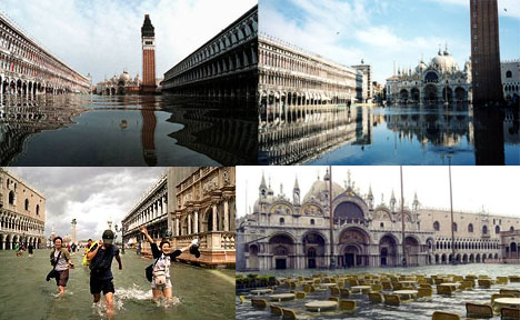 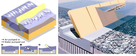 Venice, Italy: The Venice Tide Barrier Project will be the largest flood prevention project in the world. The project has been debated in one form or another for over 40 years as a way to protect this historical city-on-the-water for future generations. With Venice slowly sinking, and the water around it slowly rising, and floods always a fear, Italians have known for a long time that something needs to be done. Finally, the Prime Minister of Italy approved the second phase of the plan, including 80 hinged barriers, each approximately 6,500 square feet. 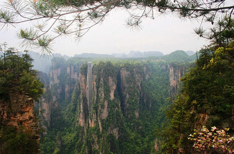 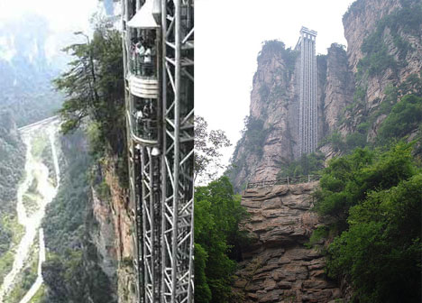 Zhangjiajie, China: The Bailong Elevator is the world’s largest exterior elevator. At over 1,000 feet tall, this elevator looms high midway up a cliff overlooking a valley far below. Moreover, the elevator is mostly glass, affording passengers a dizzying view to the depths below. There is some concern, however, about the elevator’s long-term impact on the surrounding natural environment. 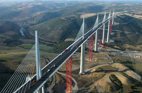 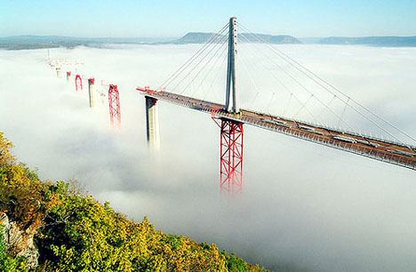  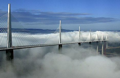 Millau, France: The Millau Viaduct is the highest bridge in the world. At almost 1,000 feet high (taller than the even the Eiffel Tower) and over 8,000 feet long it sometimes sits above the cloud line, as shown in the beautiful photographs above. The engineered wonder of the bridge itself is nearly as amazing as the view of the valley below. 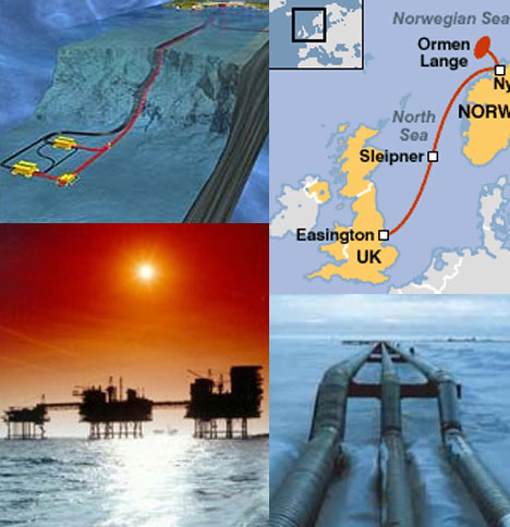  More, Norway to Easington, Britain: The Langeled Pipeline is slated to be the longest underwater gas pipeline in the world. It will ultimately supply 20% of Britain’s gas needs, connecting England to the largest gas field in Europe via 750 miles of complex underwater terrain. Engineers have had to account for subzero temperatures an stormy waters in addition to developing techniques for installing the pipeline in the first place. They are able to lay an amazing 8 miles of pipe per day. 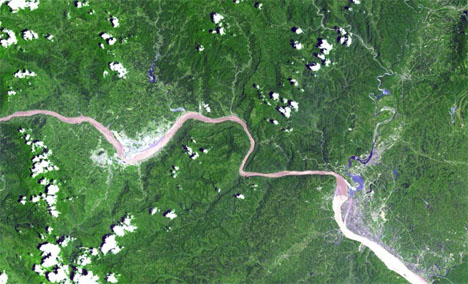 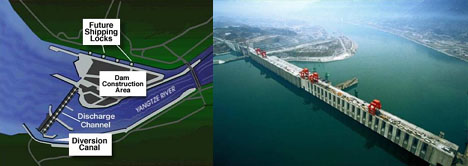 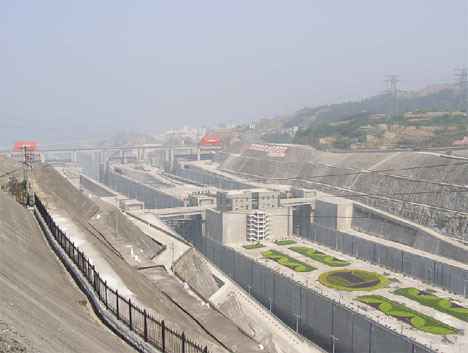 Yangtze, China: The Three Gorges Dam has drawn fire from people around the world for its role in raising water levels and displacing millions of Chinese residents in the area. As a work of engineering, however, it is unparalleled. It will be the largest hydroelectric dam in the world, 600 feet high and holding 1.4 trillion cubic feet of water behind 100 million cubic feet of concrete. This engineering wonder will also eventually provide as much as 10% of China’s vast power needs. 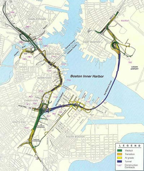 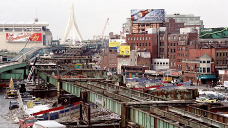 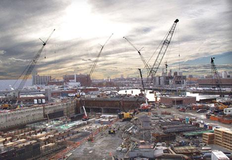 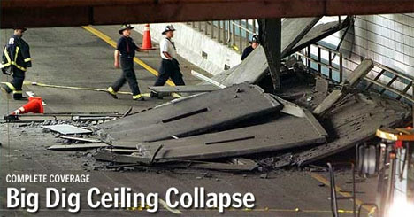 Boston, Massachusetts: The so-called Big Dig is a massive tunneling project in the heart of Boston, and is the most massive and expensive construction project in the history of the United States (at 15 billion dollars). Disaster and scandal have haunted this endeavor from the beginning, including accidents, deaths and even arrests for criminal negligence. Engineers were forced to navigate a maze of subways, pipes and utility lines in the course of the project, all with minimum disturbance to the bustling streets of Boston above. 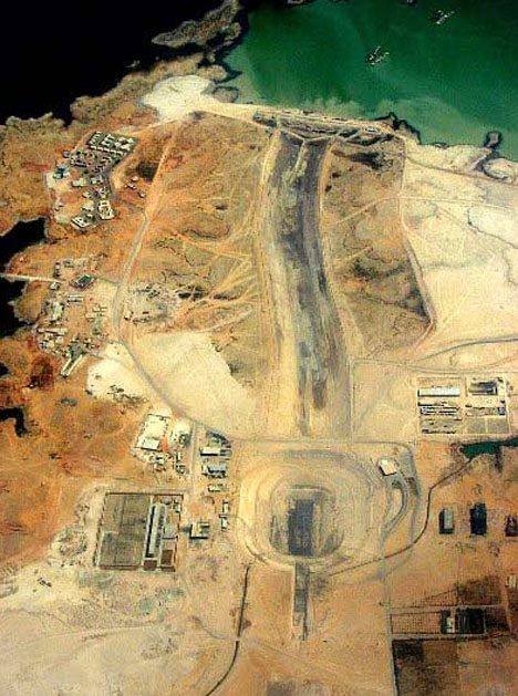 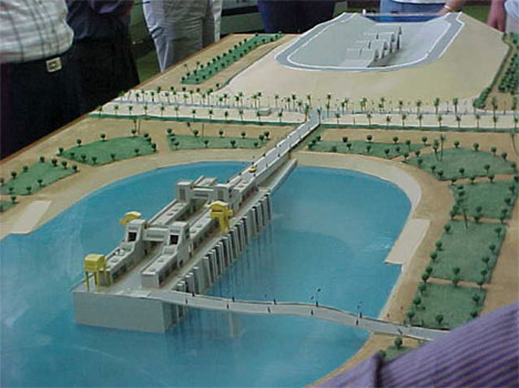 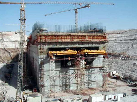 Mubarak, Egypt: The Toshka Project is an amazing attempt to convert a half million acres of desert landscape into arable land. The Mubarak Pumping Station is at the center of this effort, and will channel millions of cubic feet of water per hour. It will ultimately redirect 10% of the country’s water from the Nile and will increase the inhabitable land in Egypt by as much as 25%. BOOKS OF CIVIL ENGINEERING:
APPLIED MECHANICS: Applied mechanics is a branch of the physical sciences and the practical application of mechanics. Applied mechanics examines the response of bodies (solids and fluids) or systems of bodies to external forces. Some examples of mechanical systems include the flow of a liquid under pressure, the fracture of a solid from an applied force, or the vibration of an ear in response to sound. A practitioner of the discipline is known as a mechanician. Applied mechanics, as its name suggests, bridges the gap between physical theory and its application to technology. As such, applied mechanics is used in many fields of engineering, especially mechanical engineering. In this context, it is commonly referred to as engineering mechanics. Much of modern engineering mechanics is based on Isaac Newton's laws of motion while the modern practice of their application can be traced back to Stephen Timoshenko, who is said to be the father of modern engineering mechanics. Within the theoretical sciences, applied mechanics is useful in formulating new ideas and theories, discovering and interpreting phenomena, and developing experimental and computational tools. In the application of the natural sciences, mechanics was said to be complemented by thermodynamics by physical chemists Gilbert N. Lewis and Merle Randall, the study of heat and more generally energy, and electromechanics, the study of electricity and magnetism.[1] | ||||||||||||||||||||||||||||||||||||||||||||||||||||||||||||||||||||||||||||||||||||

Subscribe to:
Posts (Atom)